
HMTR

Hydraulic Mass Transfer Reactor

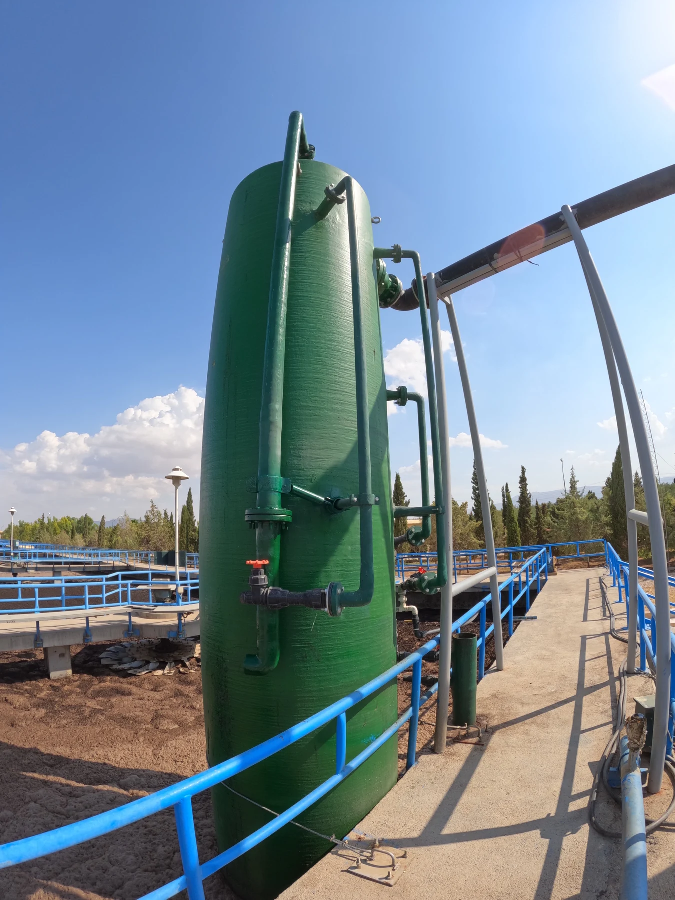
HMTR is a hydraulic reactor for dissolving air and process gases in water and other liquids. It uses the energy of liquid flow and water-column pressure to create effective gas–liquid contact. Depending on the configuration and project requirements, undissolved gas can be recovered and reused, carried into the liquid as microbubbles, or made available as compressed air.

HMTR is Koohub’s proprietary technology, with an independent architecture and development history. Its mechanism differs from ejectors, diffusers and conventional microbubble and nanobubble generators: gas–liquid contact, dissolution and separation of remaining gas are managed inside the device.

Koohub HMTR reactor

How it works

1 mMinimum required head
2.5–3 mTypical head under specified design conditions

The device operates through the head difference between inlet and outlet, supplied by pumping or natural elevation. The 1 m minimum applies to suitable passive conditions. Typical head of 2.5–3 m applies to surface discharge or injection up to 7.5 m deep at a gas-to-water volume ratio around 0.3. Deeper injection may require more head. Final head depends on flow and losses and is not the same as total device height.

  1. Zone 1: inlet and gas entrainment

    The inlet header guides the liquid into a less turbulent, directed flow. A relative pressure reduction at the gas inlet draws gas into the device.

  2. Zone 5: pressurised contact

    The gas–water mixture travels downward. Hydrostatic pressure and intensive bubble contact promote dissolution; water can become supersaturated relative to external ambient conditions.

  3. Zones 6 and 4: managing remaining gas

    Depending on configuration, excess gas is carried as microbubbles through zone 6 or separated from water as compressed gas in zone 4.

  4. Zones 2 and 3: outlets

    Under suitable conditions without strong gas or liquid reactions, the outlet generally lies in the saturation range appropriate to the conditions. Actual concentration depends on temperature, pressure, gas composition and liquid properties. The calculator provides a theoretical equilibrium estimate.

HMTR operating schematic; full view
Conceptual operating schematic. Select to enlarge.

Connections & upper assemblies

Two manufactured variants with different connection arrangements: deep-tank discharge and external installation. The plate identifies water and air connections, compressed-air outlets, sampling ports and header connections.

Upper connections of two HMTR variants; full image

Advantages & limitations

Advantages

  • Simple architecture, durable structure

    The device core has no moving parts. Its body is designed for a minimum 25-year life under specified environmental conditions. Composite construction simplifies handling and installation.

  • Dissolution inside the reactor

    Pressurised contact and intensive bubble interaction allows the liquid to approach local saturation. A large tank is not needed solely for contact, though dilution or process residence time may require volume. Deep discharge can preserve a higher equilibrium concentration.

  • Gas recovery and feed value

    Gas remaining after dissolution can be separated, reinjected or reused, or carried with the flow as microbubbles at a deep outlet.

  • Installation and mixing flexibility

    Passive or pumped, inside or outside the tank: all configurations can be installed without auxiliary support or protective structures.

  • Maintenance costs

    The HMTR core has no moving parts and requires no periodic servicing. Maintenance costs concern the pumping unit and any installed measurement or monitoring equipment.

  • Performance potential in deeper tanks

    In purpose-designed deep tanks, recovered gas is reused for dilution and microbubble injection with the aim of reducing whole-system energy demand.

Limitations

  • Tank geometry and depth

    Reduced depth and hydrostatic pressure limit dissolution benefits and microbubble contact time. Shallow or external arrangements approach surface-pressure equilibrium, reducing the benefit of pressurised dissolution.

  • Low-purity gas feeds

    For example, ozone produced by an air-fed generator has a lower partial pressure and may require more water flow for comparable mass transfer. Increased pumping flow can reduce the system’s energy advantage.

  • Device height and installation requirements

    HMTR is at least 10 m tall. Where excavation or a deep tank is unavailable, pumping costs may increase and reduce the system’s energy advantage. Device height is not the same as pump head.

  • Initial investment: CapEx

    Initial cost can exceed that of some conventional gas-injection equipment. Small installations and traditional aquaculture require an economic assessment of flow, available energy and whole-life operating cost.

Choosing a configuration

In every arrangement, zone 1 remains above the water surface. Surface discharge uses zone 2, while deep discharge follows zone 3. Zones 4 to 6 remain within the enclosed core.

Four HMTR configurations; full comparison
1

Passive, without pumping

Using elevation difference to compress air

Can be designed for large flows according to available head, site conditions and structure: diverted river water can gain dissolved oxygen while producing compressed air. A suitable distribution line can supply lake and water-body management several kilometres away. This arrangement can be assessed for large-scale compression and energy conversion, following the approach of historical hydraulic compressors.

2

Air compressor

Compressed air for pneumatic equipment

This configuration can be assessed for pneumatic equipment and deep-mine applications. Pressure depends on effective water-column height: approximately 10 m of water produces a 1 bar pressure difference. Direct water contact removes compression heat and brings the process closer to isothermal compression. Cooler water reduces the water vapour carried in the outlet air. The device core is oil-free.

3

Dissolution & mixing

Reusing air for circulation

After gas dissolution, recovered air supplies an airlift or pneumatic equipment for dilution, circulation and tank mixing. A principal intended application is oxygen transfer from air in biological wastewater treatment alongside flow management.

4

Dissolution & gas recovery

Prioritising effective gas transfer

Unused gas is separated and recirculated to the injection path to minimise losses. Corrosive, hazardous or valuable process gases require a designed closed circuit and gas-compatible components.

Development & current results

Theoretical equilibrium calculator

Theoretical oxygen equilibrium in fresh water.

535
010
03,000

Theoretical dissolved-oxygen equilibrium

At the water surface

7.7mg/L
Theoretical equilibrium at different depths
Water depthConcentration, mg/L
0 m7.7
1 m8.5
2 m9.3
3 m10.0
5 m11.6
8 m13.9
10 m15.5

Instantaneous gas consumption, gas–liquid reactions and salinity are excluded. This is a theoretical equilibrium reference; actual output depends on gas and liquid conditions and system performance.